
 SpaceWire is one of the most exciting new technologies in the space electronics industry. Previous designs used MIL-STD-1553, but are limited in speed to 1MB/s. SpaceWire (IEEE 1355.2) uses low-voltage differential signaling (LVDS) to push speeds from 2MB/s to 400MB/s. For those who are in the commercial world, it may not sound incredibly fast, but it represents a huge improvement in the harsh environment of a spacecraft. Today you can buy SpaceWire bus analyzers to see the detailed protocol, but as designs move from faster, many designers are discovering the need to look at the actual bits for signal integrity work. Fielded designs are still using speeds below 100MB/s, but in the future it will likely be pushed to its limit. In this first blog post, I will discuss how to generate the clock using the MATH system on your oscilloscope. In future posts, I will discuss simple bit level decode and more advanced jitter and timing measurements.

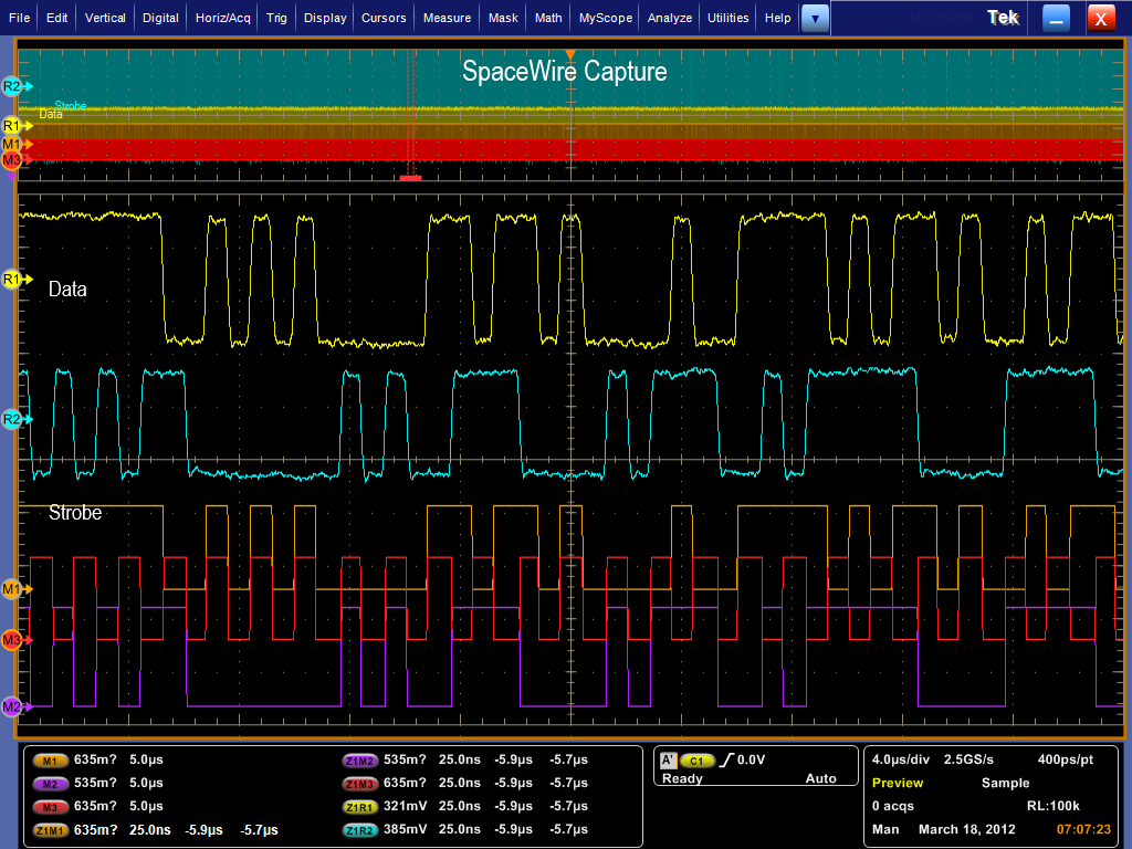
Here you see a typical SpaceWire signal. The yellow trace is CH1 and it shows the data line. CH2 is the strobe. While data is carried on CH1, the clock itself is generated by the XOR of CH1 and CH2. Whether I want to figure out the bits, create an eye, or just see the clock timing, I need to generate that XOR signal.

All of my analysis will be done with a Tektronix DPO5204, a 2GHz real-time oscilloscope that runs Microsoft Windows 7. SpaceWire signals are differential, meaning the signal has a + and - side, so I am using a TDP3500 differential probe to acquire the signals for best signal integrity.


Here you can see the result. MATH1 shows the digital version of CH1/REF1 and MATH2 shows the digital version of CH2/REF2. Note that the edges have ringing on them. This is because the channel itself is either 0 or 1. The oscilloscope interprets this quick transition in MATH as an improperly sampled edge since the display uses SinX/X interpolation, it adds some visual ringing to the edge.

To clean this up, I click on Display on the top menu, and set interpolation to Linear.

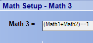 Now comes the magic - I can easily XOR these signals even though I don't have the XOR function. In MATH3, I simply add MATH1 and MATH2. If either one is high, the function adds to 1 and is true. If both are low, the function adds to 0 and is false. If both MATH1 and MATH2 are high, the function adds to 2. Since 2 does not equal 1, my function is once again false. I have implemented the XOR function with simple comparative logic.
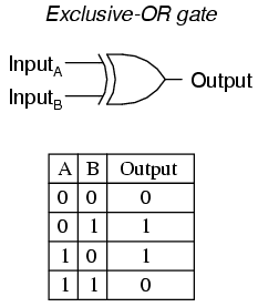
Here I have combined everything into a single MATH1 equation. Now you can also see why using VAR1 instead of a real value is beneficial. If I change between differential and single ended probes, I don't have to edit the entire equation.

Below is my result - a clock has been successfully generated from my data and strobe. Next blog post, we will discuss how to decode the Data line into 1 and 0 values for export into a text file.

Nice trick for the XOR function - cool!
ReplyDeleteThe XOR function trick is simply amazing.Nice informative post.Thanks for sharing.
ReplyDelete