

You sit at your bench and in front of you is a a function generator and a basic oscilloscope. You connect the function generator to the oscilloscope with a BNC cable and proceed to create a simple signal to measure. Surprise, the amplitude measured on the oscilloscope does not match what you set on the function generator. The sine wave may read 1V peak-to-peak (Vpp) on the function generator, and yet on the oscilloscope, it says 20Vpp or 2Vpp. Now is when you ask,
"What is wrong with my function generator?"
 |
| Tektronix TDS2024C |
Commonly the question comes from a student and he is using a low to medium performance oscilloscope with a bandwidth of 200MHz or less. Examples include the Tektronix TDS1000, TDS2000, and DPO/MSO2000, the Agilent DSO1000 and DSOX2000, LeCroy WaveAce, or really any lower cost oscilloscope about 200MHz or below.
I checked with the Tektronix technical support center, and they confirmed they get this question commonly around the start of the semester when students are taking engineering labs for the first time. However, I have seen this misunderstanding trip up even seasoned engineers in other circumstances. The common issue is that these oscilloscopes have high impedance inputs only, and do not have regular 50 ohm inputs. Behind the single BNC connector, oscilloscopes that are 500MHz and above typically have 2 input paths switched by a relay. There is a 50 ohm path for high frequency signals and active probes, and a high impedance path for passive probes. So a 2.5GHz oscilloscope will have a 2.5GHz 50 ohm path and a 500MHz high impedance path.
A lower bandwidth scope is intended to be used with a probe, so it is almost always high-impedance only. High Impedance is abbreviated 1M or High-Z on many oscilloscope datasheets. Examples of such scopes are listed below.
A lower bandwidth scope is intended to be used with a probe, so it is almost always high-impedance only. High Impedance is abbreviated 1M or High-Z on many oscilloscope datasheets. Examples of such scopes are listed below.
 |
| Tektronix DPO2024 |
 |
| Agilent DSOX2024X |
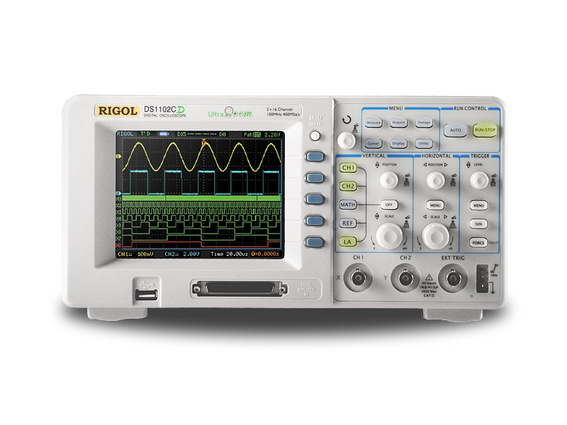 |
| Rigol Oscilloscope |
In this example, I have set a Tektronix AFG3252 to output a 1MHz sinewave at 1Vpp. Remember, the AFG is a 50 ohm device and is expecting to output into a 50 ohm system.

Taking the Tektronix DPO/MSO2000 series as an example, first I push Default Setup and then measure the peak-to-peak voltage. I am shocked to find it is not 1Vpp, but 20.0Vpp! First, note that this particular oscilloscope has a probe with switchable attenuation. As a result, the oscilloscope assumes you have a 10x probe on the front. It takes the input voltage and multiplies it by 10 in software before displaying a waveform. You need to go into the channel menu and set attenuation to 1x. Most oscilloscopes of this type cannot recognize the probe, so they often assume 10x be default.

At this point, I still have a problem as you can see below. Any oscilloscope that is high impedance only will measure 2Vpp instead of 1Vpp. The problem is that the function generator is assuming I have a 50 ohm termination. Since I am using a 1M termination (and the scope doesn't have a 50 ohm input), I will always get the 2x scaling error. Looking at the screenshot below, the Pk-Pk voltage now reads as 2.00V.

So what solutions do I have?
Here, I have gone into the AFG output menu and told it that the load is High Z. What happens? Interestingly enough, the AFG does not change its own output impedance, but what it does is calculate the right voltage assuming a high impedance load. When I go back to the AFG screen, it now says my signal is 500mV.

So I have to bring it back up to 1Vpp, and notice in the top right corner, it says Load High Z.

Now my scope display matches my function generator.

Stick this signal into 50 ohms, and it will read 500mVpp, but read it on any of the high-Z only scopes listed above, and it will correctly be scaled at 1Vpp. Bear in mind, the AFG output impedance did not change, it just adjusted its own output voltage to account for the impedance mismatch.
Also remember: higher bandwidth oscilloscopes that include a 50 ohm input will default to high-impedance when you push "default setup". So everything I said above will apply even on a 1GHz or 2GHz scope if they have not been set to 50 ohms.
 |
| Tektronix TCP202 Current Probe |
 |
| 50 ohm feed-thru terminator |
Hopefully when somebody searches for function generator, oscilloscope, and scaling, this post comes up and they quickly realize that you cannot mix a 50 ohm function generator with a 1M input scope without making the proper adjustments.
*print*
ReplyDeleteTo be posted at the hackerspace, thanks a bunch.
nice informatuve artivcle electrical services perth
ReplyDeleteI've been bitten by the TCP202 with a TPA-BNC with a DPO2024. But I got something other that a 2x scale issue.
ReplyDeleteAnd I can't use a 50 ohm feed thru with a TPA-BNC
Function generators are continuous tuning over wide bands with max-min frequency ratios of 10:1 or more, a wide range of frequencies from a few Hz to a few MHz, a flat output amplitude and modulation capabilities like frequency sweeping, frequency modulation and amplitude modulation.
ReplyDeletegenerators